NUERA Smart Camera Overview
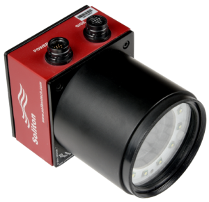
NUERA machine vision smart camera is a compact, modular and a complete vision system . With inbuilt high performance quad-core ARM processor, it is capable of running image processing algorithms & user application logic. NUERA provides flexibility to choose the image sensor resolution, lens, filter, lighting, and connectivity interfaces as per the requirement. Complete SDK (C / C++, Python) is provided including project templates and example codes to speed up the application development.
Features which make it suitable for your next generation vision systems:
- Compact Design – enables implementation of compact vision solutions
- IP67 Certified, Industrial grade – works reliably in harsh Industrial environment
- Image Sensor, Lens, Filters – flexibility to chose Image sensor (VGA, 1.2MP), Lens & Filters (C, CS, S mount)
- Integrated Ring Light – eliminates the need of external light and its strobe controller
- Inbuilt Quad Core CPU (ARM – 1GHz) – allows user to run image processing algorithms and application logic
- Open Source Software Support – Embedded RT Linux, OpenCV, C/C++, Python, WebGUI
- Various Communication Interfaces & Direct Display – 4x high speed IO’s, Gigabit Ethernet, RS232, USB, HDMI Display output
- Industry 4.0 ready – option for Inbuilt WiFi / 4G
NUERA Smart Camera Models
NUERA Smart Camera comes in two models, Standard & Pro. Standard model is IP67 certified and Pro has additional USB2.0 and direct HDMI display Interface. HDMI interface eliminates the need of PC for operator display. Optional WiFi/4G is also available in NUERA Pro model.
Power IO Connector Pinouts
| Pin Number | Function |
|---|---|
| 1 | Input 1 (TRIG) |
| 2 | Output Source / Sink |
| 3 | Output 2 |
| 4 | IO GND |
| 5 | INPUT 2 |
| 6 | Output 1 |
| 7 | RX232 TX |
| 8 | SHIELD |
| 9 | RS232 RX |
| 10 | DGND |
| 11 | Camera 24V DC |
| 12 | Camera GND |
Smart Camera Model Comparison
| Part Number | Image Sensor | Interfaces | Included Accessories |
|---|---|---|---|
| NU03STD | 752 x 480 (VGA) Global Shutter 60FPS 6.0um pixel size | RS232 (Rx, Tx) 4x High Speed IO’s Gigabit Ethernet Integrated Ring Light | Lens protection cover Ethernet Cable Power IO Cable 24V 1.5A Power Supply IP67 Enclosure |
| NU03PRO | 752 x 480 (VGA) Global Shutter 60FPS 6.0um pixel size | RS232 (Rx, Tx) 4x High Speed IO’s Gigabit Ethernet HDMI, USB2.0 Integrated Ring Light | Lens protection cover Ethernet Cable Power IO Cable HDMI, USB Cables 24V 1.5A Power Supply |
| NU12STD | 1280 x 960 (1.2MP) Global Shutter 54FPS 3.75um pixel size | RS232 (Rx, Tx) 4x High Speed IO’s Gigabit Ethernet Integrated Ring Light | Lens protection cover Ethernet Cable Power IO Cable 24V 1.5A Power Supply IP67 Enclosure |
| NU12PRO | 1280 x 960 (1.2MP) Global Shutter 54FPS 3.75um pixel size | RS232 (Rx, Tx) 4x High Speed IO’s Gigabit Ethernet HDMI, USB 2.0 Integrated Ring Ligh | Lens protection cover Ethernet Cable Power IO Cable HDMI, USB Cables 24V 1.5A Power Supply |
NOTE: Development work on 2.0/5.0MP is in progress and will be available soon.
For any further assistance, please contact our application engineer at info@balunstech.com
Mechanical Dimensions & 3D Models
Find below mechanical dimensions & 3D models of NUERA Standard and NUERA Pro models. 3D models are in step file format. Mounting plate drawings & model is also given below.
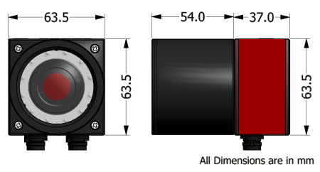
NUERA Standard Dimensions
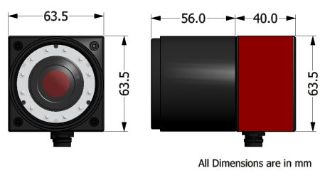
NUERA Pro Dimensions
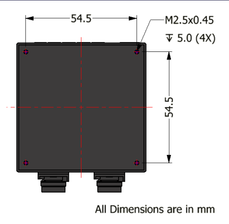
Mounting Arrangement
NUERA 3D models
-
Download Step File for Standard 3d model
Download Step file for Pro 3d model
NUERA Mounting Plate
-
Mechanical Drawing for Mounting Plate V1.0, V2.0
Download Step file for Mounting Plate V1.0, V2.0
Tests & Certifications
BalunsTech is committed to provide highest quality products, various tests and certification procedures (as listed below) have been carried out on NUERA Smart camera to ensure the best quality & reliability.
- IP67
- Temperature Test
- Vibration
- Shock
- ROHS
- ESD
- CE / FCC
IP67
NUERA standard version is IP67 certified.
Temperature Test
External test laboratory to carry out temperature test to evaluate reliability of our NUERA Smart Camera design. Temperature test starts range from 30 degree C to 85 degree C in 5 steps and comes back to -40 degree C in 5 steps. Holding time at each step was 15 minutes and total test duration was 6 hours. During the test camera was powered and streaming the live image to the WebGUI on another laptop connected over Ethernet. Camera functioned properly during the test duration and found no external physical defects after test was over.
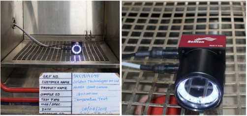
Fig.1 Temperature Chamber Test Setup
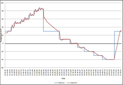
Fig.2 Temperature Graph
Vibration
External test laboratory to carry out vibration test to evaluate reliability of our NUERA Smart Camera design. Vibration profile used for the test was Sinewave vibration 1g, 5 – 2000Hz, 1 octave per minute, 4 sweeps per axis (X, Y, Z). During the test camera was powered and streaming the live image to the WebGUI on another laptop connected over Ethernet. Camera functioned properly during the test duration and found no external physical defects after test was over.
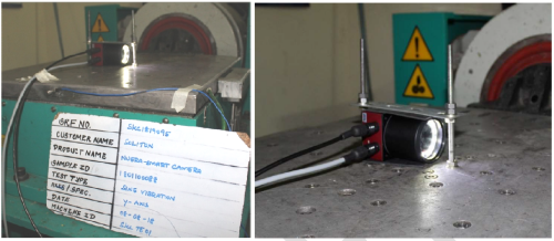
Fig.3 Vibration Test Setup
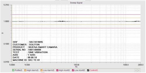
Fig.4 Vibration Test Graph
Shock
External test laboratory to carry out shock test to evaluate reliability of our NUERA Smart Camera design. Shock profile used was 10g, 11msec, 18 shocks (6 shocks per axis). During the test camera was powered and streaming the live image to the WebGUI on another laptop connected over Ethernet. Camera functioned properly during the test duration and found no external physical defects after test was over.
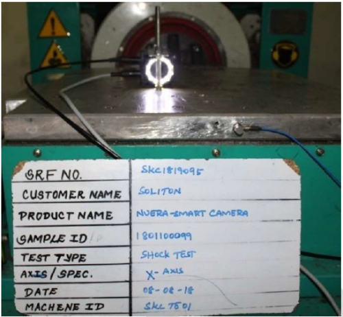
Fig.5 Shock Test Setup
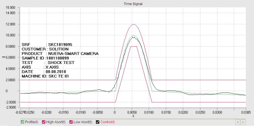
Fig.6 Shock Test Graph (+ve)
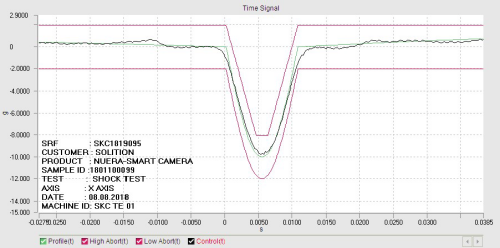
Fig.6 Shock Test Graph (-ve)
ROHS
During design phase, Balunstech has carefully selected all the components for NUERA Smart Camera and can confirm that all the components used are ROHS compliant.
ESD
NUERA by design is ESD protected but still it is recommend to take precautions while handling the camera in the field.
CE / FCC
Balunstech has carried out emission tests on NUERA Smart Camera and found results well with in the limits defined by CE and FCC. Pre-compliance testing is in progress and soon will be going for final certification test. NUERA Smart Camera is expected to get CE/FCC certification by approx. Dec 2018 time frame.
Warranty & RMA
Balunstech is committed to provide high quality, defect free products. It follows strict testing procedure during production to ensure best quality output. NUERA Smart Camera comes with standard warranty of 12 months from the date of invoice.
Warranty – Terms & Conditions
- It covers all manufacturing defects.
- Product must have used under standard operating conditions as specified in the datasheet.
- Any physical damage to the body or connectors will void warranty.
- Removing security sticker from the camera voids the warranty.
RMA
Balunstech will handle RMA within warranty period. Customers need to send detailed description of defect & the operating setup then return the product to Balunstech’s office (Bangalore, India) for further investigation. If Balunstech finds that the camera is defective, will do detailed examination of the product to determine the nature of defect and at its discretion would repair or replace the defective parts.
Why NUERA?
Thanks for showing interest in NUERA Smart Camera and willingness to spend more time to understand deeply how NUERA can add value to your Vision System.
Here are ten advantages of using NUERA Smart Camera:
- It has integrated strobe light, this eliminates the need of external light. Additionally, it has 4x high speed IO’s, RS232, Gigabit Ethernet, USB 2.0 and HDMI display output is available directly from the camera itself, so for many applications this will be a huge advantage, no need to add separate PC for operator display. All these features makes it a complete vision system.
- Option for inbuilt WiFi / 4G. One can build highly sophisticated cloud connected IoT solution or even setup a vision system to run on Opex model.
- Web Server / WebGUI helps camera and application level configuration using any device having browser. No software installation required. It can also be used for operator GUI , hence saves significant development cost and effort.
- As NUERA Smart Camera runs Embedded RT Linux, open source image processing libraries like OpenCV or any other open source libraries could be used for vision algorithm development. No extra OS license cost or image processing library license cost. For more flexibility, Balunstech has tested NUERA with Industry known MVTec Halcon Library and it works well. Customer gets the freedom of choice, whoever want to use ready libraries to save on development time, can use HALCON. Please note HALCON license need to be purchased separately, Balunstech can also bundle it along with the Camera.
- Application can be written in popular programming languages like C/C++, Python for NUERA. Balunstech provides project template for quick start where, image capture, various interfaces & IO’s handling is already given, one need to just implement the vision algorithm part.
- Free accessories like 24V 1.5A Power Supply, Power IO Cable, Ethernet cable, Lens protection cover makes the total solution much more affordable.
- NUERA standard model is IP67 certified, can work in harsh industrial environment. CE/FCC Certification is in progress.
- NUERA Smart Cameras are fully designed and manufactured in India.
- Warranty & after-sales support is provided by Balunstech directly from it’s Bangalore, India office. This helps in quick response time.
- Balunstech has more than 20 years of experience providing engineering services to various MNCs across the globe and in designing machine vision cameras since 2006. Balunstech can take up custom development projects for special requirements which cannot be fulfilled with NUERA or to further optimize design for features, size, performance, cost, etc.
Build your Vision System using Balunstech’s NUERA Smart Camera!
How to Buy
Balunstech designs & manufactures all Smart Cameras at it’s office in Bangalore, India. Get in touch with our sales team at info@balunstech.com for assistance in purchase, following process will be followed.
Recommended Prerequisite
- Go through the datasheet in details to understand the suitability of NUERA Smart Camera for your requirement.
- Reach out to one of our application engineer for assistance in selecting the right NUERA smart Camera model.
Next Steps
- Once right NUERA model is selected, please contact our sales team to check the stock availability.
- If stock is available, send the PO, against which sales team will help you with a performa invoice and account details for payment. Once payment is done, Balunstech will ship the camera as soon as possible. Generally, if stock is available, cameras will be shipped within 1-2 days.
Shipping
- Balunstech offers free shipping across India.
Unboxing NUERA Smart Camera
Congratulations on getting your NUERA Smart Camera!
Let us unbox the NUERA and explore a little bit.
Hardware Setup
In the package you will get following items:
- NUERA Smart camera
- Ethernet Cable
- Power IO Cable
- 24V DC Power Adapter
Connect the RJ45 end of Ethernet cable to your PC/Router/Ethernet Switch and circular connector end(for NUERA standard) to NUERA Smart camera. For NUERA Pro version standard, RS45 cable will be used.
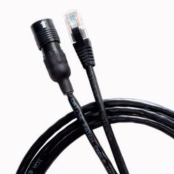
Fig 1. NUERA Ethernet Cable (for standard model)
It is assumed that you have access to a 230V AC plug to power NUERA using the 24V DC power adapter. Connect NUERA power cable’s circular end to NUERA and other end to power adapter 2Pin connector. In addition to power lines in the Power-IO socket in NUERA, you can access 2x general purpose input, 2x general purpose output and RS232 (RX, TX). Complete pin-out details are available here.
Setting up Network setting on PC
By default IP address of the NUERA Smart Camera is set to 192.168.1.221. To access inbuilt webserver called WebGUI of the Smart Camera, either PC should be connected to the Smart Camera directly through an Ethernet crossover cable or to an Ethernet switch/Local network, to which Camera is connected to. If the camera is directly connected to the PC then, the PC should be configured with static IP address. In Ubuntu, you can do this by following steps given below:
- Click on the Networks icon at the top-right corner of the desktop
- Select Edit Connections.
- Then, Add a new connection and select Connection Type as Ethernet. Give a name to this connection.
- Under the IPv4 Settings tab, select the method as Manual and click on Add button. Enter any address except 192.168.1.0, 192.168.1.1 or 192.168.1.222.
- Set Netmask as 255.255.255.0 and Gateway as 192.168.1.0.
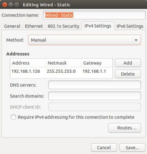
Fig 2. Network Setting on Ubuntu Linux PC
NOTE: If you plan to work with NUERA Smart camera using Ethernet crossover cable, you can check the ‘Automatically connect to this network when it is available’ option in the General tab.
Explore WebGUI
Once the NUERA Smart camera is powered up, wait for 5-10 seconds, it hosts the WebGUI. You can open WebGUI in your browser by simply entering the NUERA Smart Camera’s IP address (default: 192.168.1.221) in the address bar of any web browser (Google Chrome is the recommended browser).
On the right hand side you will see the live Camera feed and on the left hand side you will see two options:
Camera Configuration will have following sections:
- Basic Camera Information like application name, serial number, MAC ID,
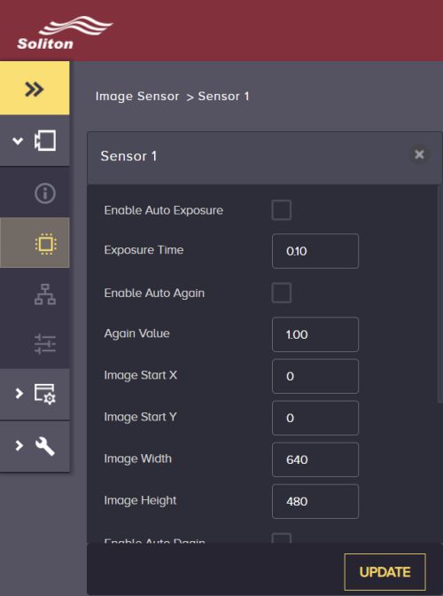
- Image Sensor settings like sensor gain, exposure time, ROI, trigger mode, etc.
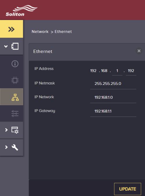
- Network setting IP Address of the camera.
- Peripheral settings like for strobe light, configuring different servers running inside.
Application Configuration will have following settings:
- Select Application type – example threshold, value, etc.
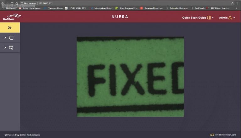
Fig 3. NUERA Smart Camera WebGUI
NUERA SDK for CPP Programming
NUERA Smart Camera has Embedded RT Linux running (version 4.1.2 with Hardfp) along with OpenCV 3.3 which gives vision solution developer complete full freedom. Open Source software support eliminates the need of Windows license fees, run-time license fees for image processing libraries.
Follow the steps mentioned below to install SDK on PC for NUERA Smart Camera:
- Prerequisites – 64bit PC with Linux OS (Ubuntu 14.04)
- Install NUERA IDE
- Create / Import New Project
- Uploading application to NUERA Smart Camera
Prerequisites
A 64bit Linux PC with Ubuntu 14.04 Operating Systems is required for the application development for NUERA Smart Camera. Click here to download Ubuntu OS.
If you would like to Install Linux on Windows Operating System then follow the instructions given below else skip and move to next section:
- Download the .iso package of the Linux distribution.
- Download Rufus or a similar tool that converts your flash drive into a bootable OS device.
- Insert a flash drive to the PC that has the memory capacity of minimum 2GB and be prepared to lose the existing data in the flash drive.
-
Open the Rufus application and select the following configuration
- Select the flash drive you inserted in the Device tab
- Select MBR partition scheme for BIOS or UEFI
- Select FAT32 under File system
- Use the default cluster size
- Name the drive as you desire
- Check ‘Create a bootable disk using ’ checkbox
- Click the disk icon next to Create a bootable disk using _ check box and select the OS Image that you want to install
- Press Start
- Allow the application to download and install a compatible version of Syslinux, if prompted
- Allow the application to write in ISO image mode, if prompted
- Allow the application to format the flash drive if prompted
- Once it is finished, restart the PC and go to Boot options menu by pressing the appropriate key in your PC
- Select the USB port to boot the OS
- Now you can try the OS without installing it. Once you decide to install, navigate to settings button on the top right corner of your desktop and select Install OS.
- Here you have a number of options to install the OS. Choose the dual boot option and allocate a part of your hard drive to the OS being installed.
- Having your PC connected will install all the latest drivers and update the applications.
- Once you are done installing and restart your PC, you maybe prompted to update your OS to the latest distribution available. But keep in mind that updating Ubuntu may not allow configure and connect to NUERA properly.
Install NUERA IDE
Follow the steps mentioned below to install NUERA IDE:
- Download the latest version of NUERA IDE Installer.
- The installer is a self extracting script which will install the required dependencies automatically.
- Please give yes for all of its prompts if you are running this installer for the very first time, otherwise choose as required.
- Once the installation is complete, a new ICON will be created on the desktop by name “Workbench for NUERA Development”.
- Once the IDE is installed, open /etc/ssh/ssh_config file in your PC to update configurations as shown below (Fig 1.) to allow communication with camera.
- To run the Eclipse based NUERA IDE, double click “Workbench for NUERA Development” ICON on desktop.
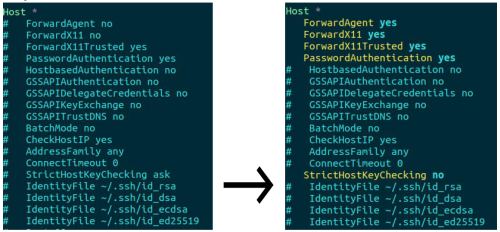
Fig 1. ssh_config file
Create Import New Project Template
Follow steps mentioned below to create / import new project template:
- Download the latest version NUERA Project Template available.
-
To import the downloaded project into Eclipse IDE, go to File >> Import, then select Existing Projects into Workspace under General category.
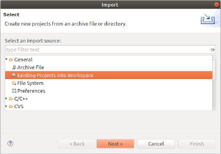
Fig 1. Eclipse IDE – Select File Window
-
Choose Select Archive File , then navigate and select the compressed project downloaded using above link to import it into the workspace. Ensure that copy projects into workspace is enabled.
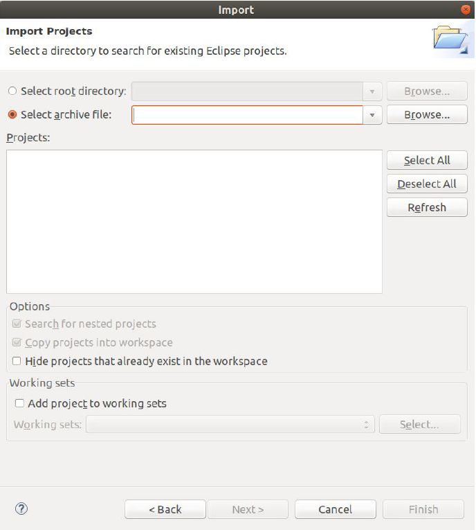
Fig 2. Eclipse IDE – Import Window
- Right Click on the newly imported sample Template Project and then select Index >> Rebuild.
- Right Click on the Project and then select Reconfigure Project.
- Now build the sample project either by using Ctrl+B or by Right Clicking on the Project and then selecting Build Project.
-
The build should get finished without any error (refer console output for the status), see image below.
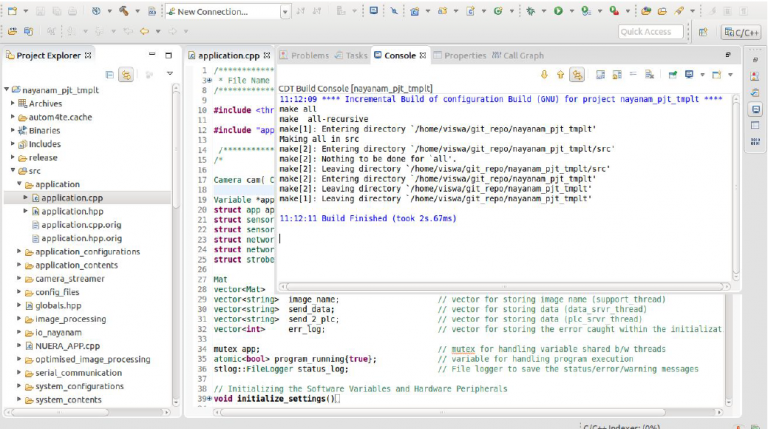
Fig 3. Eclipse IDE – Build Project
Upload Application to NUERA Smart Camera
Follow steps mentioned below to upload the application to NUERA Smart Camera using Eclipse IDE:
-
To upload the newly build application to NUERA Camera, run UPLOAD_TO_CAMERA option listed under External Tools Configuration after selecting the appropriate project.
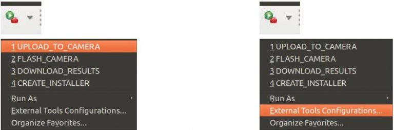
Fig 1. Eclipse IDE – Upload to Camera
-
Very first time, you may not see the UPLOAD_TO_CAMERA option under the section shown below, hence you have to select External Tools Configuration and then select the launch configuration in the left pane of the window and Click Run.
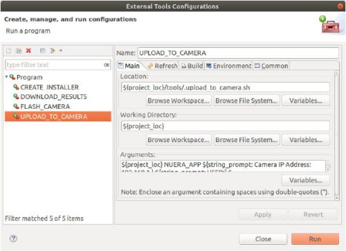
Fig 2. Eclipse IDE – External Tools Configurations
-
Enter the IP address of NUERA Camera (default: 192.168.1.221), password (default: root) and then y/n for running the application when prompted and this should upload your application to the camera and you should see the message as below without any error.
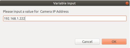
Fig 3. Eclipse IDE – IP Address Prompt
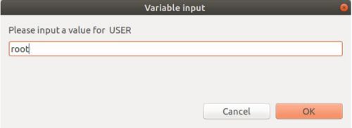
Fig 4. Eclipse IDE – Username Prompt
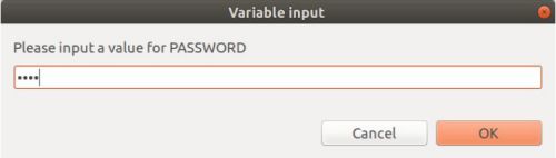
Fig 5. Eclipse IDE – Password Prompt
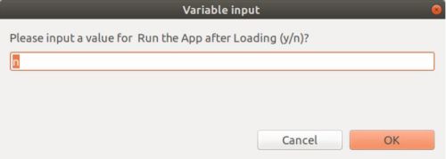
Fig 6. Eclipse IDE – Run Application Prompt
Develop New Application in CPP
New application can easily be developed using project template for NUERA Smart Camera. Let us take a simple threshold application to create a new application. First, will setup a hard coded threshold value in the application and later will try to configure that using configuration via WebGUI control. Later, based on the requirement one can add Serial interface, TCP communication, GPIO interfaces, etc.
Adding A New Image Processing API
Adding a new image processing API involves three steps as given below:
Step 1: Open the Image Processing file
Open nuera_project_template in Eclipse IDE and go to file src >> image_processing >> process_image.cpp . This can be done in the Project Explorer pane as shown below:
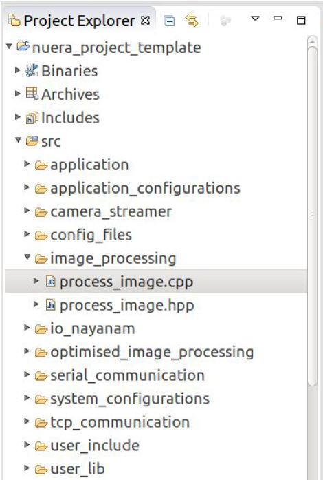
Fig 1. Eclipse IDE Project Explorer
Step 2: Edit the code
In the process_image.cpp file, scroll to the process_image function. The image processing code should be written in the process_image function as shown below:
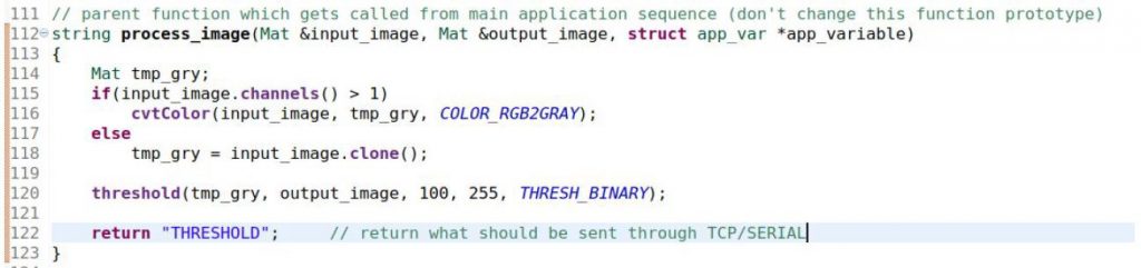
Fig 2. Image Processing Code
The arguments of the process_image function are :
- ‘ input_image ’ – the input image captured by the NUERA image sensor.
- ‘ output_image ’ – the processed image, which gets displayed on the WebGUI. Results will be stored in this image.
- ‘ app_variable ’- a data structure which contains the application variables.
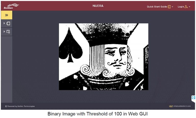
Application variables can be used to configure values . The image above demonstrates addition of a simple image processing code. Grayscale-to-Binary conversion is the image processing function added to process_image(). The OpenCV function used is threshold(), to understand threshold(), refer this .
Step 3: Upload the application to NUERA Smart Camera and see the result
Once you save this file, build the project by right clicking on the Project and then selecting Build Project. After build is completed successfully, you can Upload this project to NUERA (see here how to upload). You can see the corresponding output on the We GUI. WebGUI will show the result image which was stored in output_img buffer.
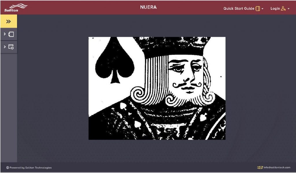
Fig 3. WebGUI running threshold applications
Adding New Application Variable & WebGUI Control
You may want to control some application variables from the GUI. For example, we may have control over the threshold intensity value given to the threshold function from the GUI. Below are the steps to be followed to introduce such a variable and add the control to the Web GUI.All of the steps can be done within Eclipse nuera_project_template.
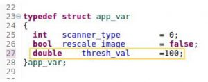
Step 1: Define new application variable
Navigate to file src >> application_configurations >> app_variables.hpp. Open the structure app_var and declare the variable that you wish to control from the GUI as shown below:
Step 2: Use the new variable in the image processing file
Navigate to file src >> image_processing >> process_image.cpp. This is where the image processing code is written. You can use the newly declared variable in the process_image() as shown below:
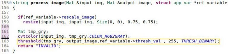
Please note, in the above code, threshold value in the threshold function is the variable ( thresh_val ) we have declared in the previous section. Similarly, any code can be added in the process_image() function with application variables which can be controlled from the WebGUI. And, any number of application variables can similarly be introduced and used.
Variables that do not need WebGUI controls can be declared in process_image.cpp file with local or global scope, whichever is needed.
Step 3: Add new element for the variable to Application Configurations XML file
Open nuera_project_template on Eclipse and go to file src >> application_configuration.xml. Now, add an element for the new variable, following the format of the existing elements, as shown in the example below:
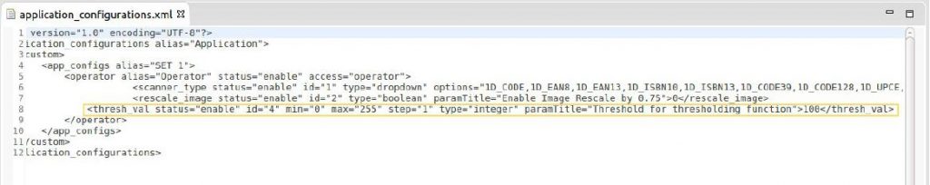
Please note, in the above screenshot, each element has an ID number (‘ id’ ). This number is used as the index of the variable in the application variable structure ( app_var ). Also, the elements in the xml file can take different values for ‘ type’. Below are the different
values of ‘ type’ which can be used and their corresponding data types:
- “string” –> str
- “integer” –> int
- “dropdown” –> int
- “radio” –> int
- “button” –> bool
- “boolean” –> bool
- “float” –> float
- “double” –> float
Notice the different types used in the XML file in the screenshot above:
Step 4: Edit the app_constants.hpp file to include newly added XML element in app variables list
Open file src >> application_configurations >> app_constants.hpp . The ID number of the newly added xml element must be linked to a new #define constant as shown in figure below:
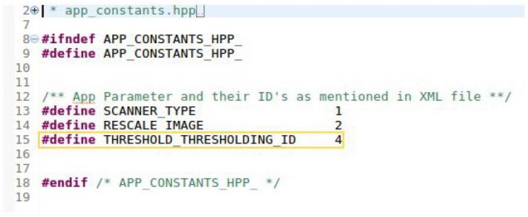
From here on, these #define constant names can be used to access the variable value, which are initialized and updated in app_var structure . For eg., var_list[RESCALE_IMAGE] gives the value of the rescale_image element in the xml.
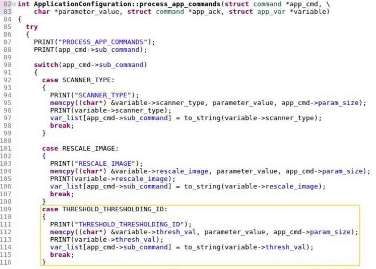
Step 5: Add Web-GUI controls for the new variable
The next step is to edit the code to get the user-given input from the GUI and update the value of the variable.
Navigate to file src >> application_configurations >> app_config.cpp. Here, use the code format used for the existing variables and add code for the new variables in
the ApplicationConfiguration::process_app_commands() as shown below:
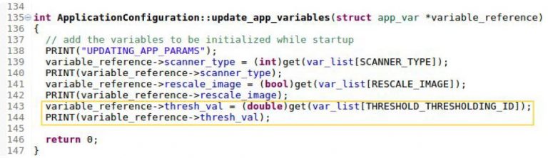
Similarly, to update the application variables, add code using the general format in the ApplicationConfiguration::update_app_variables() as shown in the code below. Give the correct type cast for your new variable.
Step 6: Upload to NUERA and see the result
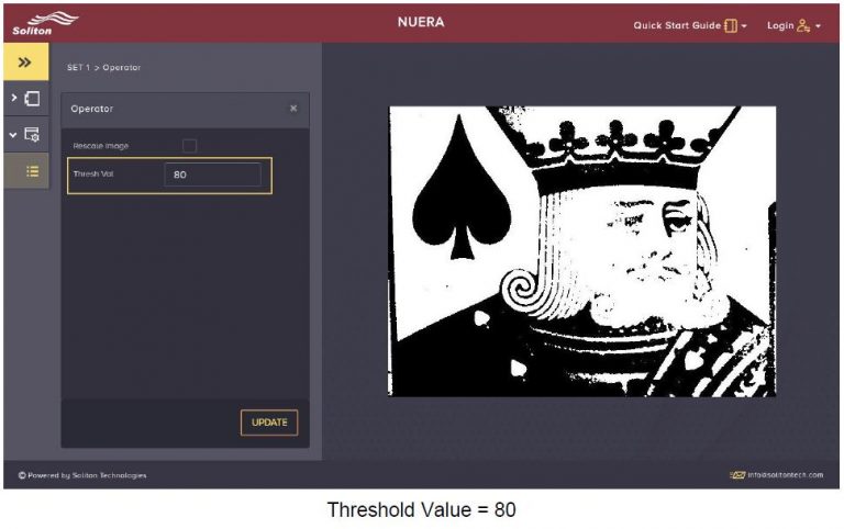
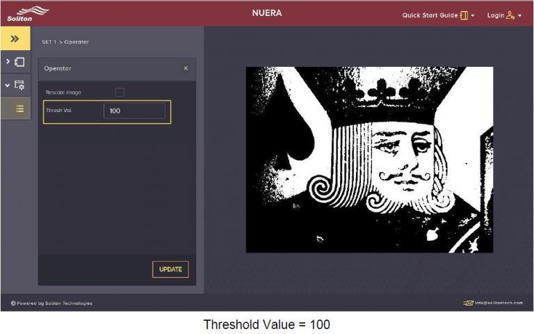
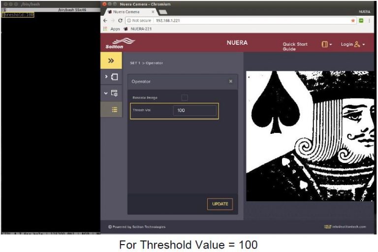
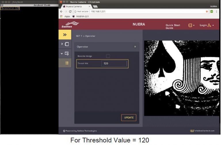
Now, once you save the files and build the project, the build will complete successfully. Then you can Upload this project to NUERA (Refer Section 3.4 of Getting Started with NUERA to know how to upload your application into NUERA). Open the WebGUI, and go to Application>> SET 1 >> Operator . Here, a control for the newly added application variables should appear. You can now change the value of the variable and click Update, and observe the corresponding output image. The configuration settings will be displayed in the web application as seen in the screenshots below:
Adding Serial Communication (RS232)
NUERA has one Serial (RS232 – Rx, Tx) communication port using which , we can send and receive serial data between NUERA and PC. This can be done by taking out Rx, Tx, GND from Power-IO cable to RS232 port of PC using 3 wire custom cable. If PC do not have an RS232 port, a USB to RS232 adapter can be used.
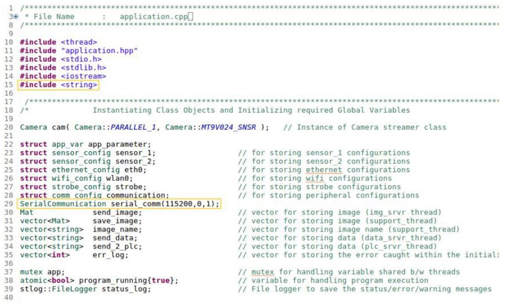
Step 1: Create an instance of SerialCommunication class
Navigate to file src >> application >> application.cpp. In the section of the code where global variables are initialized and class objects are instantiated, create an instance of class SerialCommunication named serial_comm. Here, we also define the Baud rate for the UART serial communication. #include
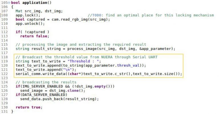
Step 2: Edit the application() in application.cpp to write data to serial port
Expand the application() in application.cpp . Here, add the code for serial communication from NUERA. For example, let us write the threshold value of the binary threshold function (which can be changed by user from WebGUI) seen in the previous section. The code is shown below:
Step 3: Install a Serial Port Terminal Software and open Port corresponding to NUERA.
Various serial port terminals are available.
For Windows PC:
We recommend Hercules SETUP utility on Windows platform for this facility. It’s freeware, and hence it can be used and shared for free. You can download the software here . After installing the Serial Port Terminal, connect the RS232 to USB cable from I/O module to the PC. Open Device Manager, and find out which COM Port is connected to the I/O module. Now, in the software, open the Serial tab, select the connected COM port, input the required Baud rate and data size and parity if required. Then select Open option.
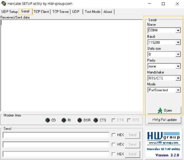
Fig 1. Serial Terminal
On Ubuntu PC:
Minicom is the most commonly used Serial Port Monitor. The steps to install and use Minicom are mentioned below:
- Open Terminal
- Install the program with: sudo apt-get install minicom
- Connect the RS232 to USB cable from I/O module to the PC
- In order to find the name of your port(s) enter this command in terminal: dmesg | grep tty
- For a USB-to-Serial adapter, one may see: [ 0.000000] console [tty0] enabled, [ 5.065029] usb 4-3: pl2303 converter now attached to ttyUSB0. What we are interested in is the name of the serial port. In this case, it is ttyUSB0. We will need this in order to use Minicom.
-
Next, in the terminal, enter: sudo minicom -s
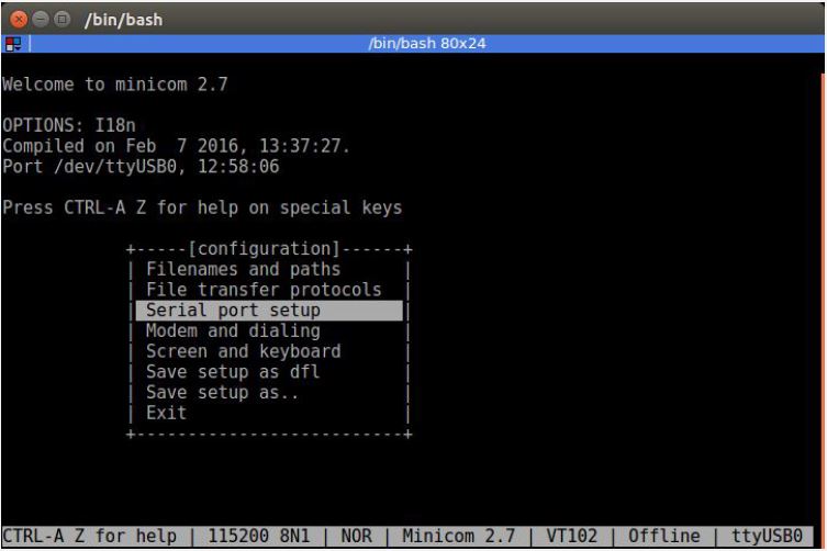
-
Choose “Serial port setup’. Then, adjust the Serial Device to that as seen in the previous step: A – Serial Device : /dev/ttyUSB0. In the same menu, input the Baud rate, data size and parity bits are specified.
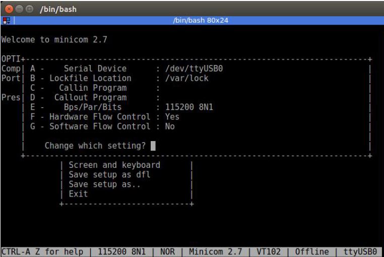
- Once configured, select “Save setup as dfl”, which will save these as the default configurations for future connections (/etc/minicom/minirc.dfl). Once saved, choose Exit, and you will see minicom prompt.
Step 4: Update NUERA and observe output:
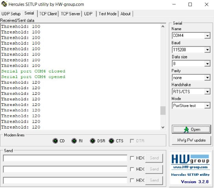
Once you save the code file as mentioned in Step 2 and build the project, the build will complete successfully. Then you can Upload this project to NUERA. In the Serial Port terminals (in Ubuntu / windows, whichever the camera is connected to through the RS232 port), you can see the threshold value being printed continuously. If you update the value of threshold(through GUI), the same will be reflected in the serial port terminal screen. The serial output on Hercules is shown below:
Open terminal on ubuntu and type minicom to open the application. The output on Minicom is shown below:
Adding GPIO Interface
NUERA Standard / NUERA Pro has inbuilt 2 inputs and 2 outputs, both are fast GPIOs, 24 volt compatible and optically isolated.
One input is dedicated for fast external trigger and other one could be used for application logic. User can control two GPIOs for external device control like for relay, panel lamp, solenoid valve, rejection system, etc
One can easily extend more no. of IOs using external RS232 or Ethernet based IOs extenders.
Following code can be used in the application for setting GPIO outputs:
   //to set GPO 1
Set_GPO_1_High();
Set_GPO_1_Low();

//to set GPO 2
Set_GPO_2_High();
Set_GPO_2_Low();
Following code can be used in the application for checking the status of GPIO input:
//to check status of GPI 2
unsigned char input_status = 0;
Check_GPI_2_Active_Status(input_status);
Adding TCP Communication
NUERA has Gigabit Ethernet on device and can send and receive data to/from another device/PC through TCP sockets. There are two ways of doing this:
- Create new TCP Server.
- Use the already developed TCP Server (PLC, Image, Data, Command) in the NUERA project template to send and receive command/data/images or communicate to PLC by simply enabling then in WebGUI.
Creating New TCP Server
In order to create new TCP server/client connection follow simple steps given below:
Step 1: Create an instance of TCPCommunication class
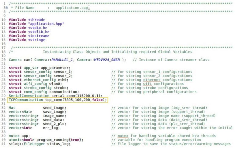
Navigate to file src >> application >> application.cpp. In the section of the code where class objects are instantiated, create an instance of class TCPCommunication, defining the server port number , buffer size (based on the size of data to be sent/received) and TCP timeout (typically 200 in ms) as shown in image below.
Step 2 : Start Server in initialize_settings()
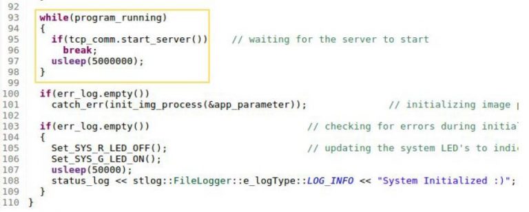
Before writing the application code, the server must first be initialized. This is done in the initialize_settings(). This code first checks whether whether any client wants to listen to the server and then, after a small delay, it enters the server application. The code must be added as shown below:
Step 3: Edit the application() in application.cpp to create a TCP server
Expand the application() in application.cpp . Here, add the code shown in the yellow box in the image below:
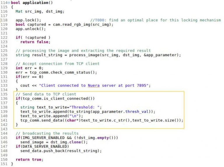
In this code,
1. check_comm_status() – checks for connection requests from clients and establishes the connection.
2. is_client_connected() – is used to find if the client is connected. In this example, the threshold value of the binary threshold function is sent via TCP to a TCP client (a TCP client software for PC is introduced in Step 5).
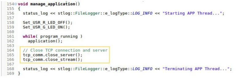
Step 4: Close TCP Connection. After communicating with the client, the TCP server must be closed. This is done in the manage_application() as shown below:
Step 5:Update NUERA and observe output
Now, once you save this file and build the project, the build will complete successfully. Then you can Upload this project to NUERA and you can observe the corresponding output on Hercules (Refer Section 3.4 of Getting Started with NUERA to know how to upload your application into NUERA).
Step 6: Set Up TCP Client
We recommend Hercules SETUP utility on Windows platform for this facility. You can download the software here. After installing Hercules , connect the PC to the same network as NUERA.
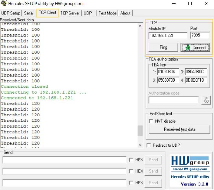
Step 7: Configure TCP Client and Observe the Result
Now, in Hercules, open the TCP Client tab, enter the IP Address of NUERA in Module IP field and the server port number (used in Step 1) in Port field as shown in image below. In the example code, notice server port number is 7895. Then click Connect button. The threshold values will be received by this client and printed as seen in the image below:
Configure existing PLC Server
NUERA project template offers readily available data server, command server, PLC server, image server in order to exchange different type of information through TCP Communication.
Follow the steps given below to enable PLC server.
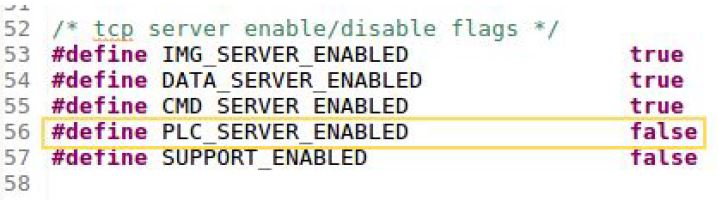
Step 1: Enable PLC Server (if not already enabled)
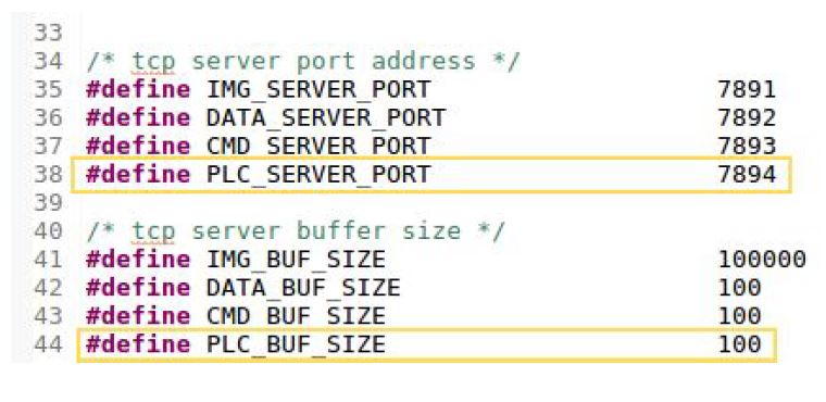
The PLC server can be enabled or disabled by using the definition PLC_SERVER_ENABLED in sys_constants.hpp:
Step 2: Configure Data Server (if needed)
In TCP, the server listens for connection requests from clients at a specific port. By default, the Port Number for the PLC server is given in sys_constants.hpp . Navigate to file src >> system_configurations >> sys_constants.hpp. Many constants are defined in this header file. Find PLC_SERVER_PORT. By default, it is defined as 7894. This can be changed as per your requirement. Remember that in Step 4, we
will use this port number as the TCP client end to connect to this PLC server. The Buffer Size and Data Timeout of the data server can also be changed in this file:
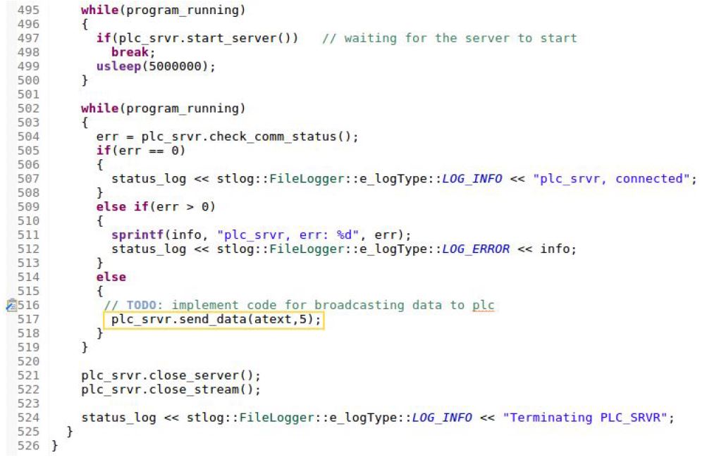
Step 3: Update code in the PLC Server Function
Navigate to file src >> application >> application.cpp. Find and open the manage_plc_srvr() . Using this server, we can send control data to a device from NUERA which can be used for applications like starting and stopping of a motor, etc. The PLC server can be enabled or disabled by using the definition PLC_SERVER_ENABLED in sys_constants.hpp . The code is shown below:
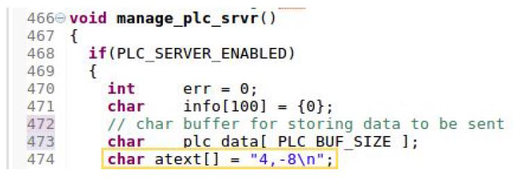
Call the send_data() , passing the character array as first parameter and number of characters as second parameter, to send this message through the network to the other device using TCP. The code needs to be added at the location shown below:
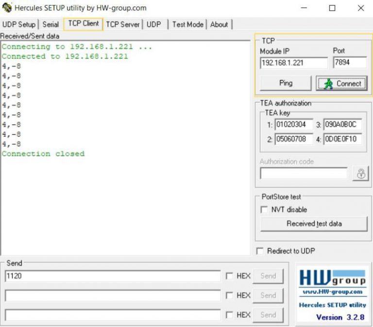
Step 4: Observe Output (on Hercules)
Hercules is used here in place of a PLC TCP client. Connect a Windows System to the same network as NUERA. Open Hercules on the Windows System. Go to the TCP Client pane. Set the Module IP as the IP address of the NUERA camera. Set the Port field according to the data port as set in Step 2. Then, click Connect button. After a “Connected” message, the data we are sending from the Nuera camera will be received by the TCP client and displayed on the screen as shown below:
Configure existing Image Server
NUERA project template offers readily available data server, command server, PLC server, image server in order to exchange different type of information through TCP Communication.
Follow simple steps given below to configure Image server.
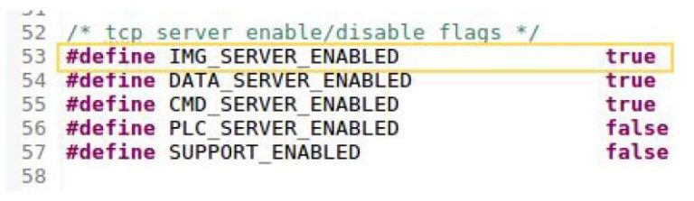
Step 1: Enable Image Server (if not already enabled)
The image server can be enabled or disabled by using the definition IMG_SERVER_ENABLED in sys_constants.hpp.
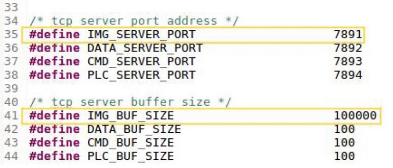
Step 2: Configure data server (if needed)
In TCP, the server listens for connection requests from clients at a specific port. By default, the Port Number for the Image server is given in sys_constants.hpp. Navigate to file src >> system_configurations >> sys_constants.hpp. Many constants are defined in this header file. Find IMG_SERVER_PORT. By default, it is defined as 7891. This can be changed as per your requirement. Remember that in Step 4, we
will use this port number as the TCP client end to connect to this image server. The Buffer Size and Data Timeout of the data server can also be changed in this file.
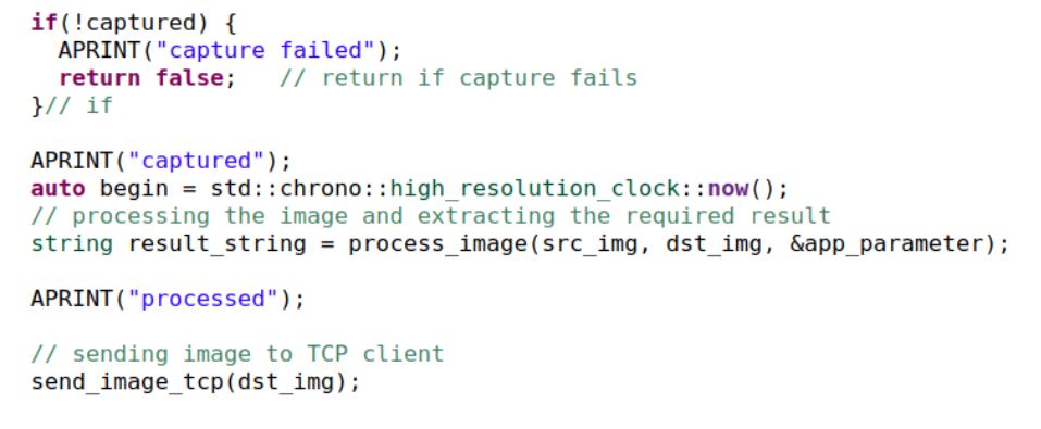
Step 3: Add code to send image
Navigate to file src >> application>> application.cpp. Call the send_image_tcp(), passing the image(Opencv Mat) which has to be sent to the TCP Client or the other device using TCP. The code needs to be added at the location shown below:
Step 4: Observing Output on TCP client
The application GUI which runs on the PC can be added with a TCP client to receive the image sent by NUERA and display the same.
Configure existing Data Server
NUERA project template offers readily available data server, command server, PLC server, image server in order to exchange different type of information through TCP Communication.
For the purpose of communicating data with a PC, a data_server has been created in the NUERA project template. As shown in the following steps, by simply enabling the data server and calling the send_data(), you can program NUERA to send data to PC.
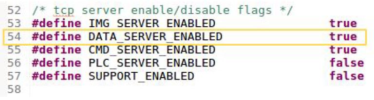
Step 1: Enable Data Server (if not already enabled)
The data server can be enabled or disabled by defining DATA_SERVER_ENABLED as true or false respectively in sys_constants.hpp.
Step 2: Configure Data Server (if needed)
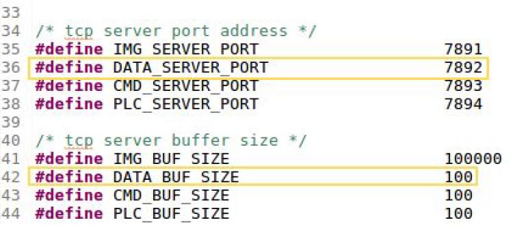
In TCP, the server listens for connection requests from clients at a specific port. By default, the Port Number for the Data server is given in sys_constants.hpp. Navigate to file src >> system_configurations >> sys_constants.hpp. Many constants are defined in this header file. Find DATA_SERVER_PORT. By default, it is defined as 7892. This can be changed as per your requirement. Remember that in Step 4, we
will use this port number as the TCP client end to connect to this data server. The Buffer Size and Data Timeout of the data server can also be changed in this file.
Step 3: Add code to Send Data
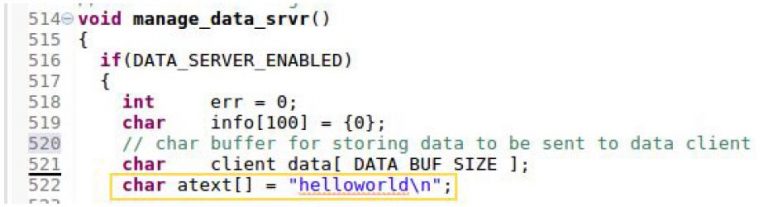
Navigate to file src >> application >> application.cpp. Goto manage_data_srvr() . Add the message you want to send through TCP to a character array. An example is shown in image below:
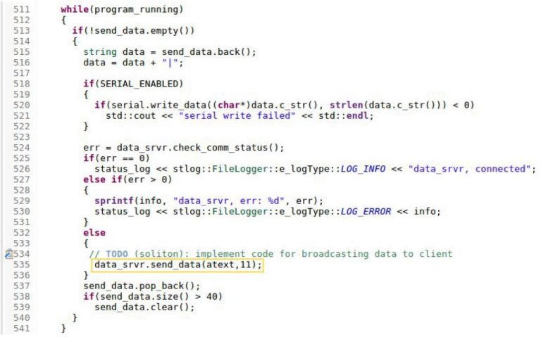
Call the send_data(), passing the character array as first parameter and number of characters as second parameter, to send this message through the network to the other device using TCP. The code needs to be added at the location shown below:
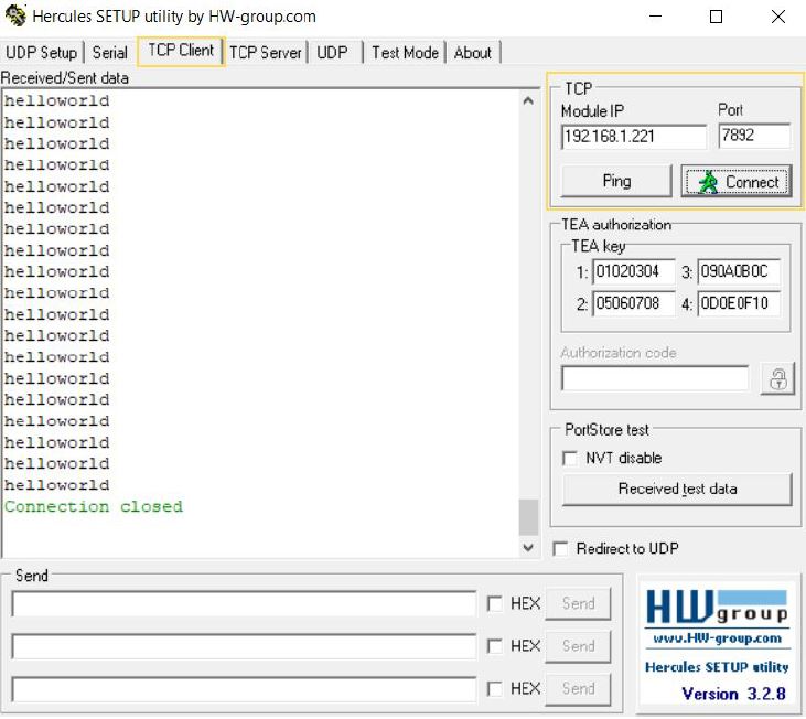
Step 4: Observe output (on Hercules)
Connect a Windows System to the same network as NUERA. Open Hercules on the Windows System. Go to the TCP Client pane. Set the Module IP as the IP address of the NUERA camera. Set the Port field according to the data port as set in Step 2. Then, click Connect button. After a “Connected” message, the data we are sending from the Nuera camera will be received by the TCP client and displayed on the screen as shown below:
Configure existing Command Server
NUERA project template offers readily available data server, command server, PLC server, image server in order to exchange different type of information through TCP Communication.
Follow simple steps given below to configure Command Server.
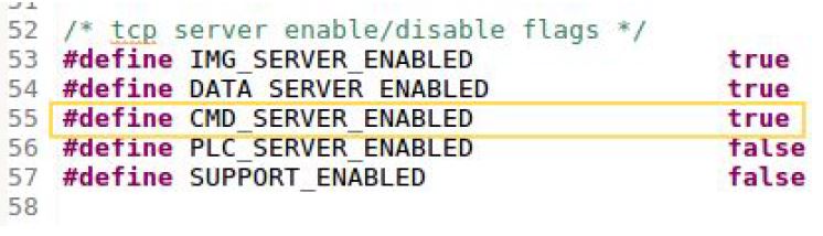
Step 1: Enable Command Server (if not already enabled)
The command server can be enabled or disabled by using the definition CMD_SERVER_ENABLED in sys_constants.hpp.
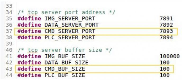
Step 2: Configure Command Server (if needed)
In TCP, the server listens for connection requests from clients at a specific port. By default, the Port Number for the Command server is given in sys_constants.hpp. Navigate to file src >> system_configurations >> sys_constants.hpp. Many constants are defined in this header file. Find CMD_SERVER_PORT. By default, it is defined as 7893. This can be changed as per your requirement. Remember that in Step 4, we will use this port number as the TCP client end to connect to this command server. The Buffer Size and Data Timeout of the data server can also be changed in this file.
Step 3: Add code to Receive Command
Navigate to file src >> application >> application.cpp. Find and open the manage_cmd_srvr(). The Command server can be used to receive commands from the user, and perform the command appropriately. The code is shown below:
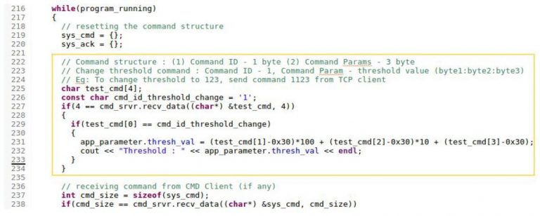
Call the recv_data() , passing the character array as first parameter and number of characters as second parameter, to receive a command through the network from the other device using TCP.
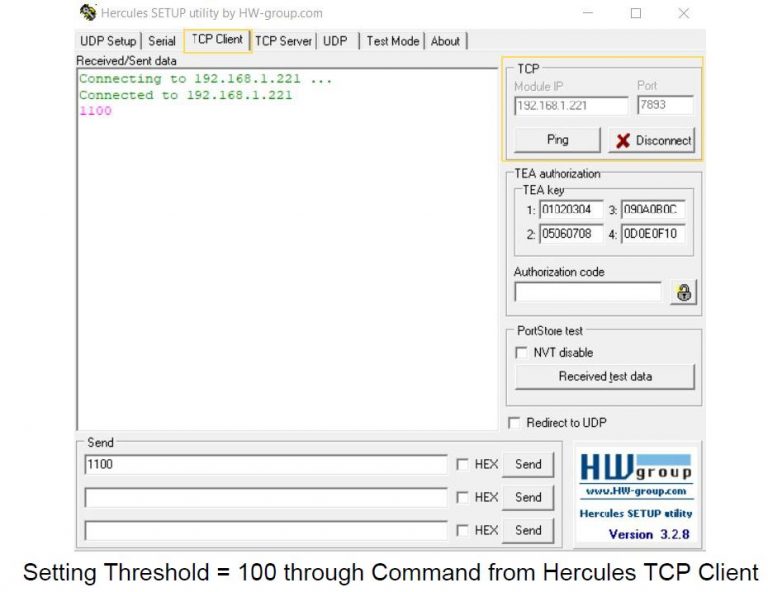
Step 4: Observe Output (on Hercules)
Connect a Windows System to the same network as NUERA. Open Hercules on the Windows System. Go to the TCP Client pane. Set the Module IP as the IP address of the NUERA camera. Set the Port field according to the data port as set in Step 2. Then, click Connect button. After a “Connected” message, the data we are sending from Hercules will be received by the NUERA camera and the threshold value is updated as can be seen in the images in web GUI
NUERA SDK for Python Programming
NUERA Smart Camera also supports Python as programming language. OpenCV functions can be called using Python code. Balunstech provides free project template so that developers can start building their application easily.
NUERA has Embedded RT Linux running (version 4.1.2 with Hardfp) along with Python 3.5m and OpenCV 3.3. One can directly start writing application in Python, no additional installation is required.
Develop New Application in Python
One can develop application in Python for NUERA Smart Camera. OpenCV function will be called inside Python code. Balunstech provides free project template so that developer can start easily and build their application.
In this section we will share details about how to configure sensor, capture image, use Serial port, Ethernet, GPIOs, TCP servers, etc. We will be adding details soon.
NUERA Fixed Mount Barcode Reader
Balunstech has launched it’s Industrial Fixed Mount Barcode Reader for 1D & 2D (QR Code, Data Matrix) barcodes using it’s NUERA Smart Camera platform. NUERA barcode reader can be used in many applications like packaging inspection, logistics, product identification, etc.
Some of the key benefits to customers are:
- Industrial Grade, IP67 certified (dust and waterproof)
- Single barcode reader for all 1D/2D barcode reading requirements
- No software installation required for configuration
- Inbuilt Barcode validation support
- Maximum flexibility with various communication interfaces
- Supports different barcode size and working distance needs
- No external hardware IOs for rejection mechanism
Key Features are:
- Various popular 1D/2D barcode symbologies are supported
- Easy to use web interface is provided for quick one-time setup
- Multiple communication interfaces like Gigabit Ethernet, RS232 for string output
- Two digital outputs for the rejection mechanism
- One external trigger input and another general purpose input for custom application need
- Various field of view options are available based on barcode size and working distance
- Direct display interface, inbuilt WiFi on request
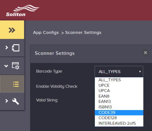
Supported Barcode Symbologies:
ID Barcode: UPCE, UPCA, EAN8, EAN13, CODE39, CODE128, Interleaved 2of5, ISBN13, Pharma code
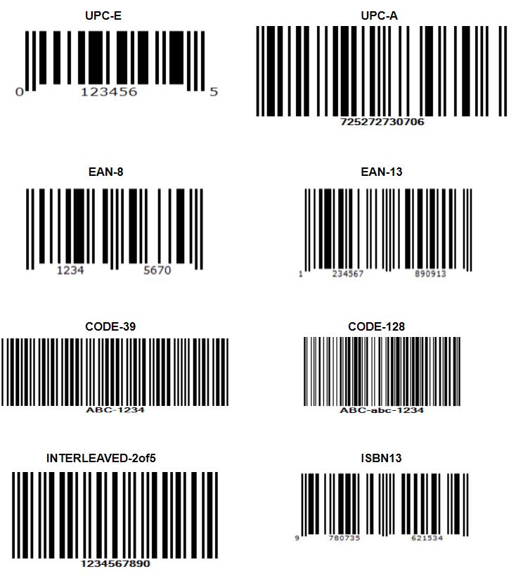
2D Barcode : QR code, Data Matrix, PDF-417

Various configuration options are available as given below:
1. Setting the ROI, Image Sensor Configurations, External Trigger
2. Ethernet IP Address Setting
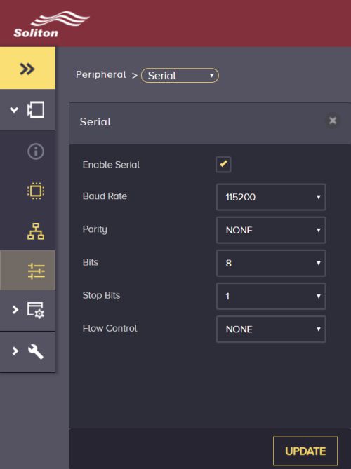
3. Serial Port Setting
4. Barcode Symbology Selection, Master Barcode to Compare
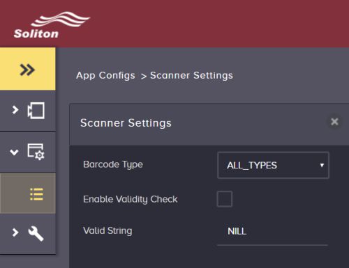
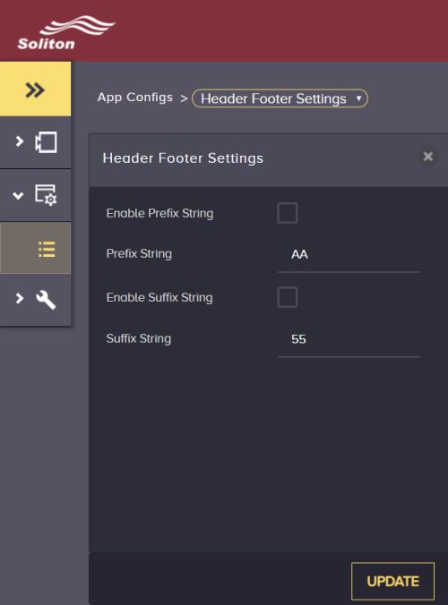
5. String output option – prefix or suffix
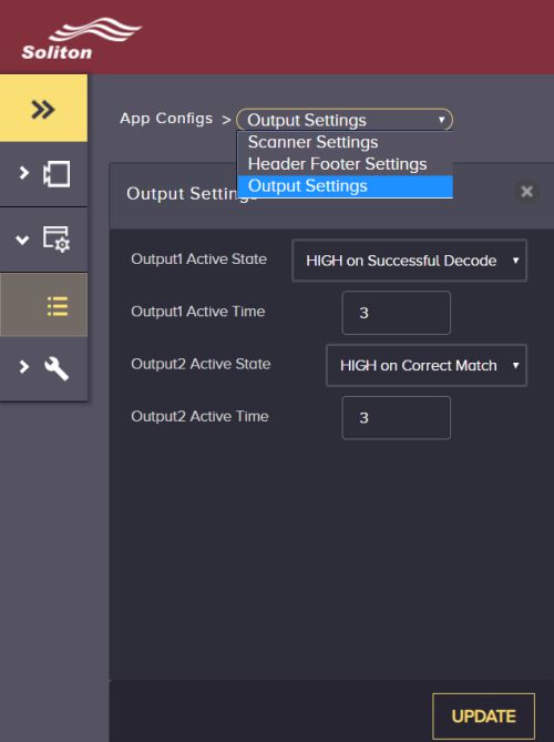
6. Two Digital Outputs configuration (good, bad output, validation output)
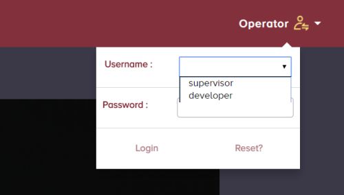
7. Login Control (Default – Operator)
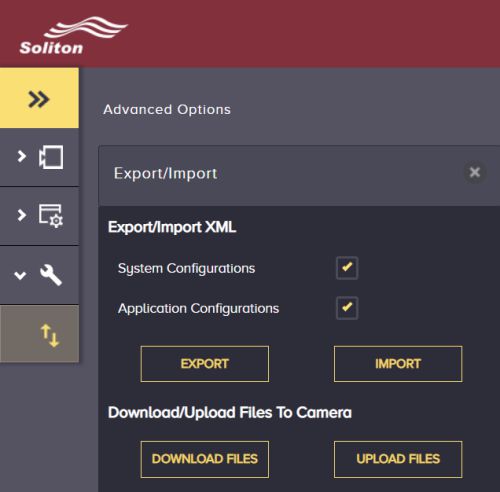
8. Advanced options – Import/Export Configuration | Download / Upload Files
Power IO Connector Pin-outs
| Pin Number | Function |
|---|---|
| 1 | Input 1 (TRIG) |
| 2 | Output Source / Sink |
| 3 | Output 2 |
| 4 | IO GND |
| 5 | INPUT 2 |
| 6 | Output 1 |
| 7 | RX232 TX |
| 8 | SHIELD |
| 9 | RS232 RX |
| 10 | DGND |
| 11 | Camera 24V DC |
| 12 | Camera GND |
Balunstech offers customized vision based solution for OEM requirements, get in touch with us at info@balunstech.com. For more technical support contact our application engineer at info@balunstech.com.
![]()
Our Products
Copyright © All rights reserved